For this tutorial you need:
- Cognex camera setup correctly
- laptop with insight explorer
- robot to calculate the worldpoints
- worldpoints that CAN’T MOVE so make sure they are fixed to your table or tape a piece of paper with the points taped down to your tabletop.
First you need to connect your camera to your laptop, u can see the Cognex tutorial for this.
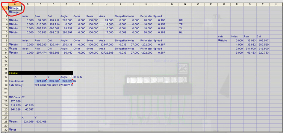
After that you need to make an image using the image function in the Cognex. Which you insert at the top of the excel window. See picture below:
comments.
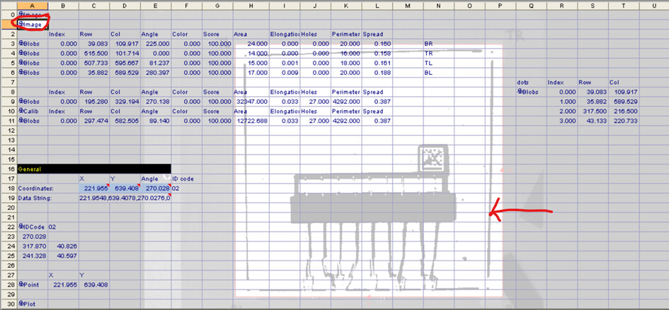
This will be your normal picture without any filtering on it using the acquire image function, as you can see we will project blobs and other functions on this so that we can easily check if the Cognex software works the way we want it to.
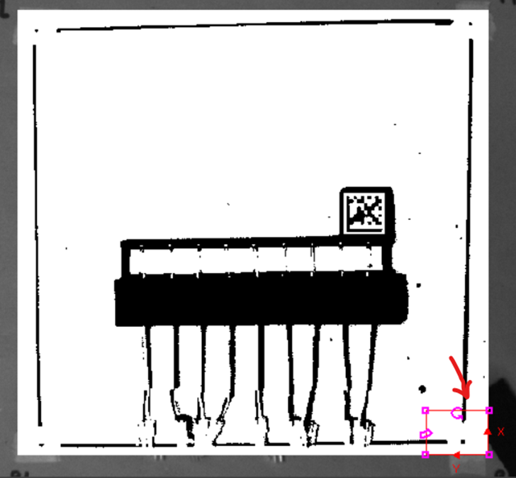
Next step is to make a filtered image. We use the PointFilter function for this. If you click on the point filter image and you made the filtered image black and white like we did it should look like this:
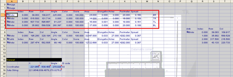
as you can see we created a square on a piece of paper and we had the camera only focus on the piece of paper u can see in the white square with the red lines. We also have drawn some lines so we can see where to place our workpiece in, and we have some small dots in the 4 corners. These 4 dots are our world points.
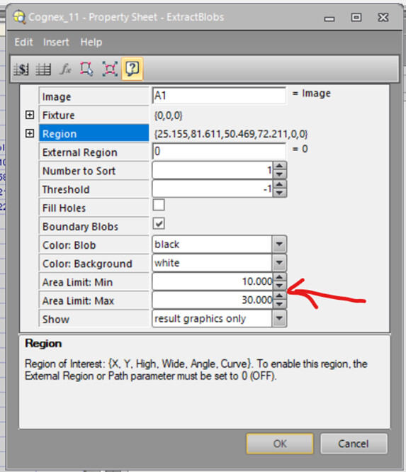
The next step is to detect the small dots in the corner (the worldpoints). We use the blob function for this. Now keep in mind that we need to be very precise, so we use this calibration only the compensate the small movements in the camera’s position for example if someone bumped into the camera and it wiggles a bit, than we can correct it using this method. If u have a moving camera, for example attached to a robot arm, you might need to configure your blob function a little differently.
We detect the blobs in the corners separately, so we created a blob function for the bottom left (BL), bottom right (BR), etc. Then to make sure the blob doesn’t detect the wrong point, we set the blob function only over the specific area we expect the point to be:
We can do this because our camera is on a fixed position and moves very slightly so we make the area as big as the tolerance we need. This is the part u might need to change if you have large movements. I would recommend using a few data matrixes instead of just some points because then you can recognise which corner the camera is looking at. This will solve the problem we had where we didn’t know which corner we were looking at.
We also had to adapt the size of the blob we were expecting because the blob would sometimes detect the boundery lines instead of the worldpoints. The points we expected were about 20 pixels large so we set the blob area boundaries from 10-30 pixels:
We did this 4 times for all our world points:
After this you want to use a property sheet calib function to calibrate the worldpoints:
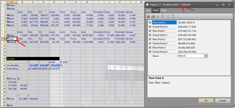
In this function you can add the pixel point (which you can get from your blob function), and bind it to the coordinates of the robots worldpoints:
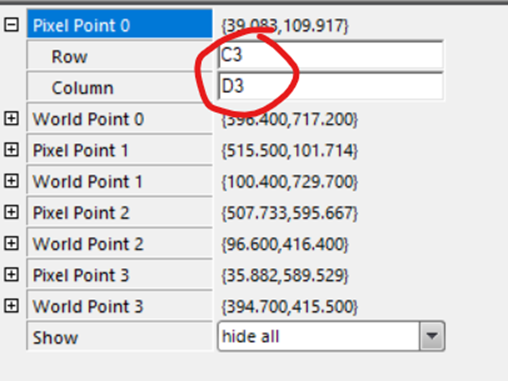
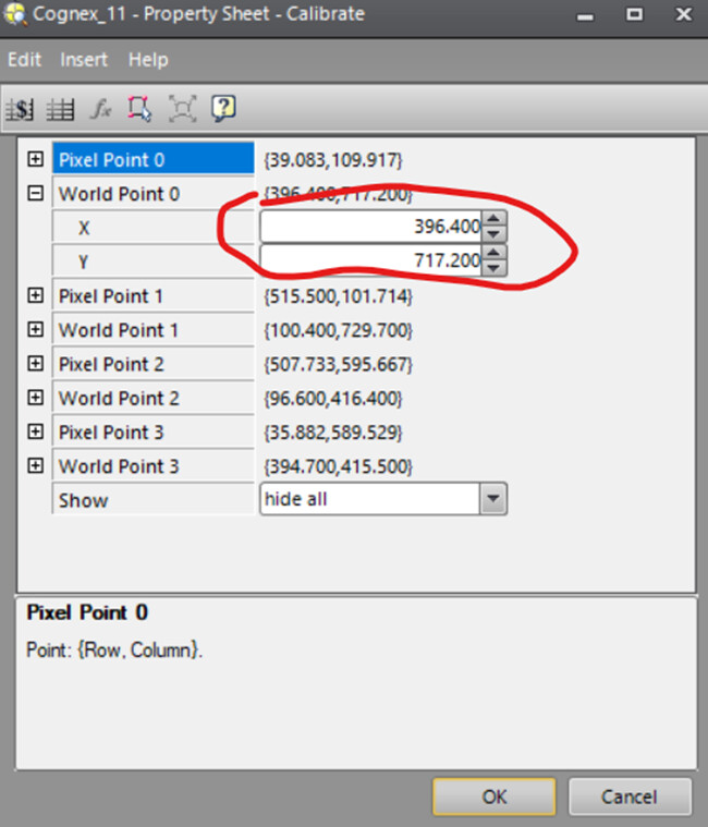
As you can see you can import the values directly from the cell the blob put the values in. Just make sure you don’t mix up the X and Y value’s and that you don’t put the wrong world point to the wrong blob value. As you might notice I didn’t tell you how to get the world points from the robot. This depends on what type of robot you are using. But usually there is a function like on the UR robots where u can get the current coordinates of the robots position using the get_actual_pose command. What you do to get the worldpoints is you move the robot head with the center on top of your point on you table or paper, do this very precisely otherwise the robot will always calibrate itself a little bit off, than you get the actual pose using the correct command for you robot. WRITE THE COORDINATES DOWN! And don’t forget to name your points so you know which coordinates belong to what points. I recommend using a square like I did and name the points: Bottom Left (BL), Top Left (TL), BR and BL.
After this you can enter the coordinates in the calib function under the tab worldpoints:
If you followed the steps correctly, the cognex camera should now calibrate itself to the correct worldpoints. U can now use this calib to transfer the pixelpoints of your workpiece to actual robot points u can send to the robot. This was the end of this tutorial, I hope it helped you. Good luck with your project!
If you want to discuss this topic or if you have questions, reply in the comments.