How to design a fingerbox
Required software
:
The software used to design a fingerbox is Autodesk Inventor. Inventor is free to use for students, click on this link to find out how to gain access and install this software: https://www.autodesk.com/education/gateway?sorting=featured&filters=individual.
Important
Assumptions
This How-to assumes you know the basics of Inventor. This guide also only shows how to make a fingerbox from a part that has already been designed. This how to explains how to create ‘fingers’ to join two edges of a part together, after that you will be able to create fingers for all of the edges of your part.
Example part
In this example we want to join two wood plates, as seen in the image:
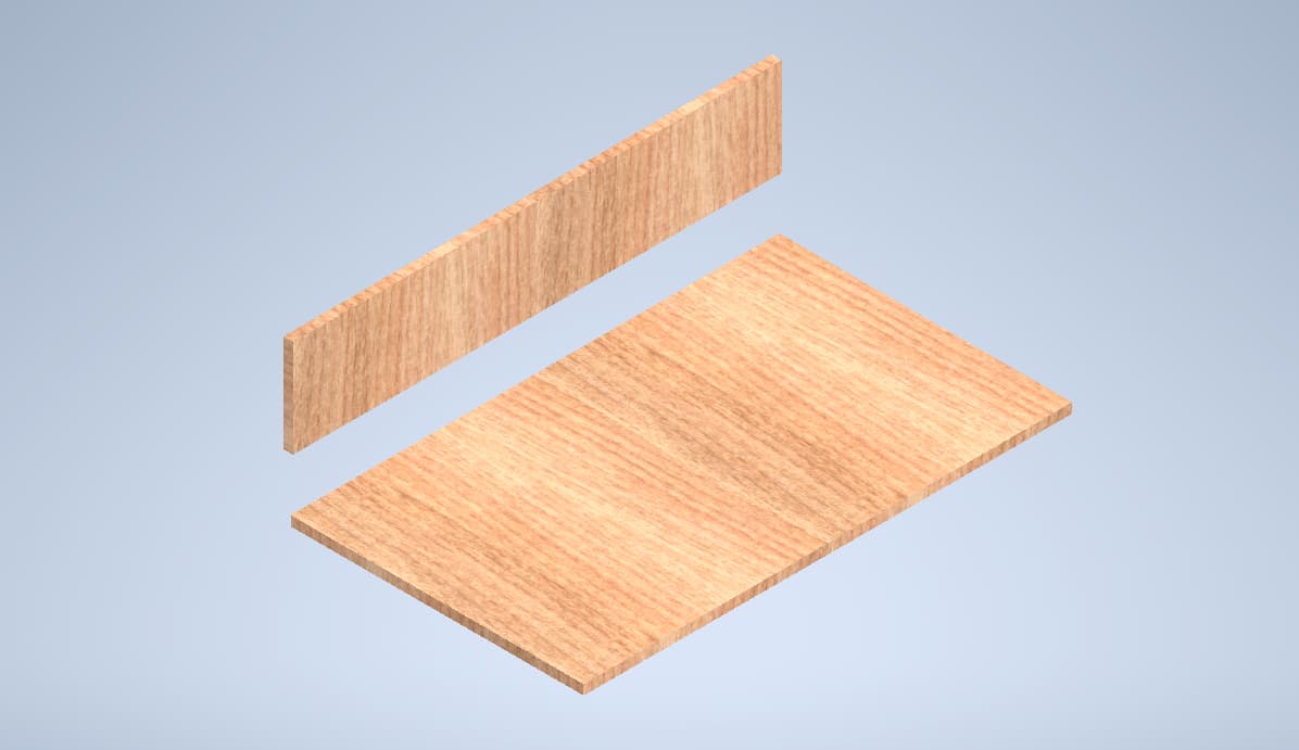
Make sure that both parts are fully defined, so that no measurements can change while you join both parts.
Part 1
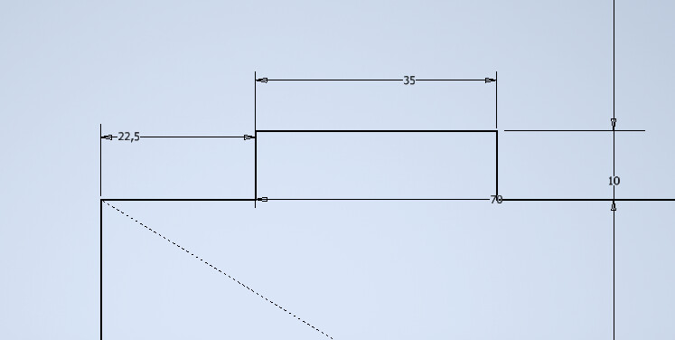
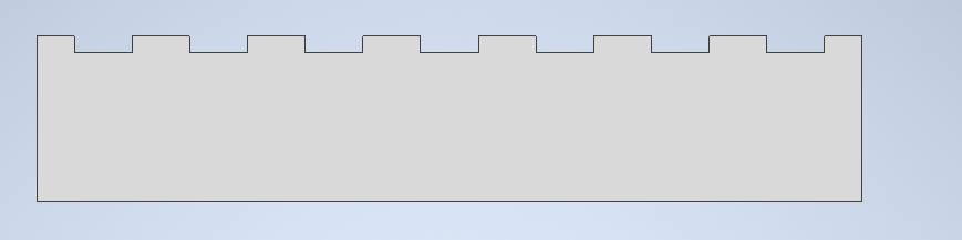
Enter the sketch of the first part. Sketch a ‘finger’ on the edge you want to join. Define the height of the finger to the thickness of the plate of part 2. The width of the finger is less important as long as it is in the range of 10-40 mm. See the image for reference.
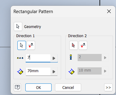
To create the other fingers, we use the ‘rectangular pattern’ tool.
- First select the 3 sides of the finger.
- Click on the arrow at ‘direction 1’
- Click on the line where you want the fingers to be.
- Make the distance between the fingers double the width of the finger.
- Fit as many fingers on the edge as possible using trial and error.
- Click OK
- Extrude all the surfaces.
Now part 1 is finished.
Part 2
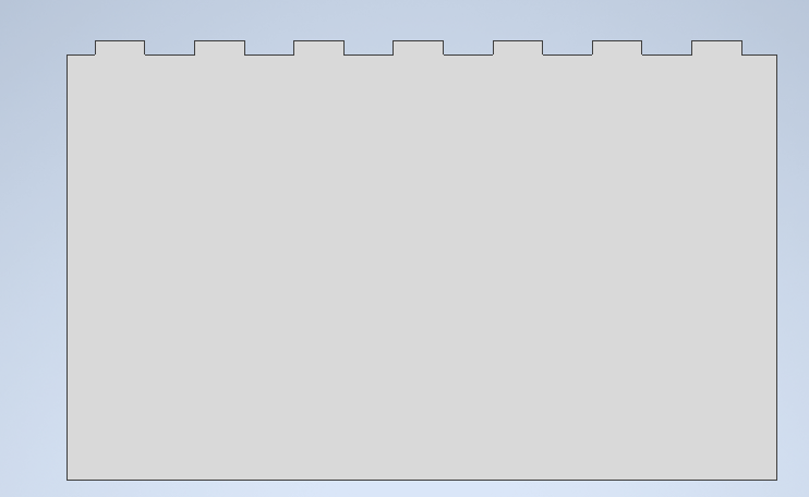
For part 2 we do the exact same, but inverted.
- Sketch the finger in the part instead of on top of the part.
- Define the distance between the edge of the finger and the edge of the part the same length as part 1.
- Use the rectangular pattern the same as part 1.
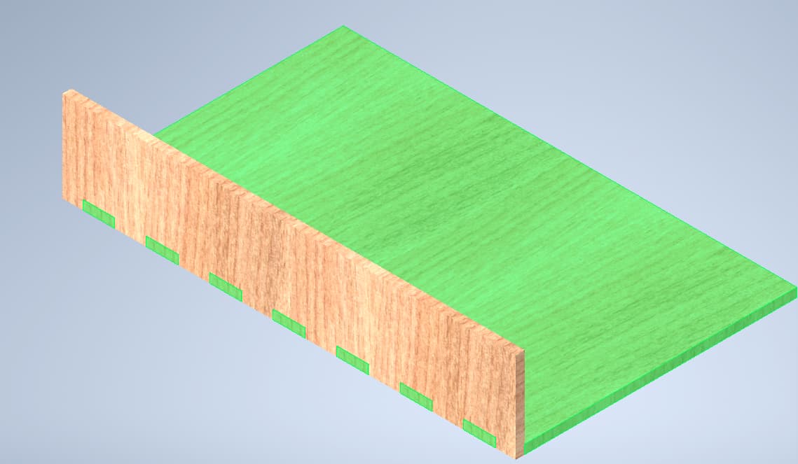
- Extrude everything but the fingers.
The result will look like this.
Now you can constrain the two parts in an assembly to verify you modelled the two parts correctly.
.
*How-to by @Job_Valkenburg *